
 How Wings Work
Introduction
According to Zdravkovich (2003), airfoil or wing airfoils are constructed to generate lift to the aircraft and an upthrust force that is same and equal to the mass of the aircraft. Again Zdravkovich stated that the weight of the aircraft should be in the opposite direction that of the flowing wind. To ensure thrust force generated by the wings is used to lift the aircraft's weight. According to him, flying airfoil reduces air pressure at the top surface of the wing while, generating pressure beneath the wing.
The mass of air surround the atmosphere is not all that much. Because, on the earth surface mass of air weighs is estimated to be 1.2 kg per cubic meter. It's because the atmosphere is a relatively thin layer around the Earth surface with approximation of one hundred kilometers thick. Air becomes thinner as one goes above atmosphere towards space until there is no air at all. Thus, it due to gravity forces that pushes air above the atmosphere towards the earth surface that forces it at the earth surface and keeps it within planet called the earth.
When airplane moves through the air, it pushes the air out of its runway using round leading front. As the air in front of the airplane gave way to it, the airplane moves forward at high speed leaving space behind. A heavy and cold mass of air moves forward due to airplane front push, and a fragile layer of hot air due to friction moves backward over it. Thus, air is pushed away from the front of the airplane to fills the space behind.
Thus, there is a lot of the pressure of the air surrounding aircraft wing that we live, without realizing it (Bertin & Cummings, 2009, pg 198). This highly pressurized air is from the atmosphere in a part of space, which is a thin layer around the Earth. The pressure at sea level is estimated to be one kgf (kilogram-force) per square centimeter that is an approximation of 10,000 kgf per square meter. Thus, reducing the pressure above one square meter wing by twenty percent requires pressure force reduction from 10000 kgf up to 8000 kgf. When pressure beneath the wing is ten percent more than at the top of the wing, it means wing will need more upward thrust force of 10,000 * 10/100 = 11000 - 8000 = 3000 kgf. But, if the wing is large enough it will lift a heavy aircraft up the ground.
Also, according to Coanda effect front of the wing is an explosion, and on top back of the wing is an implosion. According to Clancy (1975), the effect is much more on top of the wing. Coanda effect also states that explosion air moves to the directions of the area of implosion, establishing air in motion, over a curved surface. Coanda effect strength increases when there are more effect of the explosion at the top of the airfoil, and mass of air flows in all surfaces of the implosion at high motion.
Question One
Misconception Regarding the Role of Viscosity
According to Coanda effect, mass of airflow in the boundary layer that is formed when cold and hot air meets each other shows the capability of the airflow to go through the cambered upper surface. However, this idea of viscosity is not in par with the physics of cambered surfaces. But, it’s in par with the pressure gradient created due to momentum balance caused by the air flow above wings.
Misconception Regarding Pulling Down of the Flow
According to Coanda effect, it not correct to suggest opinions which state that the flow of air at the top surface area of the wing cause sticking effect to the aero wing and can be pulled down to stay at the surface of the wing. Because is not in par with the gasses law that states that air should be at pressure that is negative so that air can be pulled (Hurt, 1960, p 256). Thus, flow of air to divert it movement over the top surface, air must be forced beneath airfoil. So that the differences in pressure of hot air and cold air flows on the top surface and the flow of air at the top of airfoil is small against the atmospheric pressure.
Misconception Regarding the Coandă Effect
The effect is way an accelerated liquid at a high speed to be always attached to the next curves surface a part from the air flow due to room air into the motion. For example, when air in motion blown over a curved surface, it sticks to that surface. This high moving speed air swallows air from the boundary layer and the surface to its path forming area with low air pressure. Because the air with weight resists movement directions change
But, Coandă effect has been used wrongly to explain why and how air remains sticking to the top side of the wing. But, the top side of the surface flow has complications, because of mixing layer and beneath the flow is calm. These demonstrations are not in par with the whole flow of air at the top of the wing.
Question Two
Wing work well when the air on top of it is put in motion at increasing speed backward and downwards. The bottom air of the wing is put in motion at increasing speed a bit downwards and a bit forward (Gregory and Mark, 1995, pg 980). With higher pressure in front of airfoil, much lower force at top surface of wing and a bit higher pressure on the bottom of the wing to accelerate wing motion.
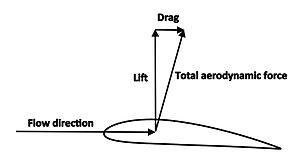
Figure 1: Showing How Lift Is Generated
Exchange of higher pressure area from the front to the bottom is achieved by the wing airfoil when the area of the explosion is below, and the area of implosion is above. Also, it achieved by tilting the airplane cord so that the airplane leading edge is above the trailing edge, and opposite direction that of air. Leading edge must be round and not pointed at the front to minimize pressure creation and to increase angle of attack. Also, the trailing edge tilted downwards and should not be positioned horizontally to increase motion of the air downwards to generate force up.
According to Hurt, (1960), the lift force of the aircraft depends on the designed shape of the wing. Thus, an aircraft to generate the lift force air foil should be curved at the center to increase camber and have a flat beneath to increase surface area volume ratio.

Figure 2: showing types of airfoil
From figure 2 above camber surface area, volume ratio is increased so that it can generate lift at zero angles of attack. Also, airplane chord line like in figure 2 below must be tilted a bit and not positioned at horizontal to reduce force and friction at the leading edge. While, the trailing edge should be facing downwards to offset forces and friction of flowing air.
Question Three
An aerofoil is shaped round and not pointed at the front to minimize pressure creation and to increase angle of attack.
According to Mulley (2004), an aerofoil is thicker in the middle to increase the maximum lift coefficient.
An aerofoil is pointed at the back to generate air flow in the streamline form and minimize friction that is caused by direct wind to the airplane leading part.
An aerofoil is flat with camber at the middle due to the air at upper surface of airfoil is at higher speed compared to that from below the wing.
Question Four
House brick can not generate lift because it can not change the angle of attack. Because the optimal lift to drag, ratio will not be created by bending the house brick.
Saucer generates lift due to motion generated by electrodes that cover its body surface area.
Football generates lift through Magnus effect that is seen in a spinning ball as it curves away from its principal flight path when hit.


Question Five
There are two commonly known types of drag parasitic drag and induced drag. And the following are their differences;
According to Anderson (2008), parasitic drag is a drag established by parts of an airplane that do not generate lift such as rivets. However, there are other three types of this drag that include form drag due to leading edge areas of the airplane and streamlining of the body of the airplane minimizes it. Skin friction drag which is a results of flowing air passing against the airplane wing surfaces and making those part smooth reduces it over the surfaces rough body. Interference drag due to disturbing of air in motion on an airplane body and filleting of interference areas reduce it.
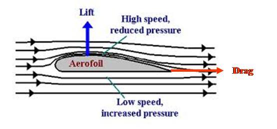
Figure 3: Showing How Drag And Lift Affect Aerofoil
According to Anderson (2012), introduced drag is a drag due to airplane part that create lift such as its wing. It is developed due to cost of lift. Induced drag is not increased by speed of the airplane but decrease in speed.
Question six
Boundary layer
Boundary layer is caused by air in motion along the top surface area of the wing that generates turbulent air flow and smooth air flow. According to figure 4 below turbulent air flow generate roughness and friction to the camber while, smooth air flow does not. Due to turbulent air flow and smooth air flow friction created forming a small layer area with less airspeed called the boundary layer that becomes thicker and thicker from the leading edge to the trailing edge. Also, boundary layer can be created due to vortex generators placed at perpendicular angle at any part of the wing.
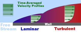
Figure 4: Showing Laminar and Turbulent Air Flow
Question Seven
According to Anderson & Eberhardt (2001), wingtip vortices are rotating air that is in the opposite direction as the wing generates lift. When airplane is generating lift one of the wingtip vortexes start at tips of every air foil because they are every where in the body pat of airplane except at wing tips. Wingtip vortices are due to lift generation and high pressure at the above and lower pressure below. Differences in pressure cause air to flow beneath and up the surface area of airfoil in round manner resulting to vortex and a low-pressure. Wingtip vortices cause wake turbulence that can cause an accident to other aircraft using the same runway. They also cause induced drag and the imparting of the downwash that cause three-dimensional lift generations.
Question eight
Common formula for lift is = CL × ½ pV2 × S for example, Lift = (0.5) * 0.55 * 0.002315 * 100 * 100 * 6 = 38.2 pounds.
Common formula for drag is Drag = CD × ½ pV2 × S for example, calculating the drag force on wall-to-wall wing drag = (0.5) * 0.0075 * 0.002315 * 100 * 100 * 6 = 0.5 pounds.
Where, CL is the lift coefficient due to angle of attack. CD is equal to drag coefficient, and S is equal to total surface area of the wing. V is equal to aircraft's velocity squared, and p equal to density of air.
Both lift and drag depends on the increasing motion of air and also, they depend on air density.
Conclusion
In conclusion, lift of a wing is generated by a pressure difference between the top and bottom surfaces Curved top surface that covers a greater distance compared to the flat bottom edge. That allows air to move increase its mition at the top surface area of a wing increasing upper presure than it below. An aerofoil is shaped round and not pointed at the front to reduce the leading edge pressure buildup and helps keep the air attached as the airfoil angle of attack increase.
According to Mulley (2004), an aerofoil is curved to increase lift generation coefficient. And tapered at the rear to enhance streamline of air flow and to reduce friction that is caused by direct wind to the airplane leading part and avoid air flow separation from wings. Also, due to turbulent air flow and smooth air flow friction created forming a small layer area with less air speed that becomes thicker and thicker from front area to back area. Moreover, wingtip vortices are due to lift generation. Differences in pressure cause air to flow beneath the wing and to the top surface of the wing in a circular manner resulting to vortex and a low-pressure.
Lastly, exchange of higher pressure area from the front to the bottom is achieved by the wing airfoil when the area of the explosion is below, and the area of implosion is above. Also, it achieved by tilting the airplane cord so that the airplane leading edge is above the trailing edge, and opposite direction that of air. Leading edge must be round and not pointed at the front to reduce the leading edge pressure buildup and to help keep the air attached as the airfoil angle of attack increase. Also, the trailing edge tilted downwards and should not be positioned horizontally to increase motion of the air downwards to generate lift.

